Verified MATLAB & Simulink Project

Battery Energy Storage Based Microgrid Using MATLAB Simulink

BESS Microgrid Using MATLAB Simulink | VSC Control & Grid Integration – MATLAB Simulation Video
YouTube Watch Full Simulation Free Preview
MATLAB R2020a - R2024b
Zero Convergence Errors
Simscape / SimPowerSystems
Need This Simulation?

Get in touch with our PhD MATLAB simulation team for customized code, parameters, or complete thesis models.

Talk to Simulation Expert
What we offer:
  • Custom MATLAB/Simulink solutions
  • 1-on-1 Expert consultation
  • Flexible pricing & 100% bug-free guarantee

Project Methodology

  1. Microgrid Model Development:
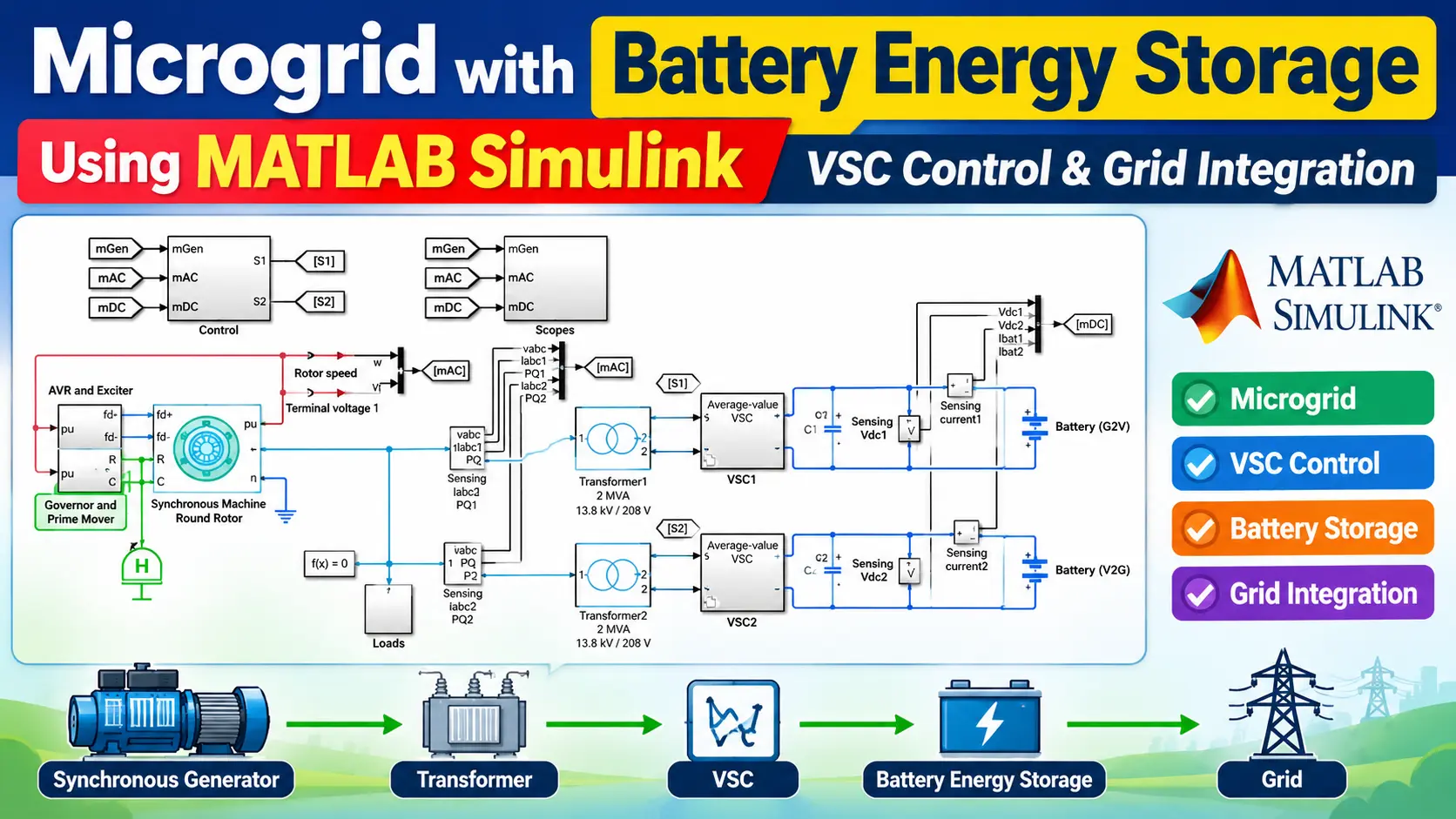
    A microgrid is developed in MATLAB Simulink consisting of a battery energy storage system, DC-link capacitor, VSC, AC filter, point of common coupling (PCC), AC load, and utility grid. The components are interconnected to study the operation of the BESS under grid-connected conditions.
  2. Battery Energy Storage Modeling:
    A battery model is incorporated with suitable voltage, capacity, initial state of charge (SOC), charging current, and discharging current parameters. The battery SOC and power are continuously monitored during the simulation.
  3. DC-Link Configuration:
    A DC-link capacitor is connected between the battery system and VSC to provide a stable DC voltage for converter operation. A DC-link voltage controller is implemented to maintain the reference voltage during changes in battery and grid power.
  4. VSC Implementation:
    A three-phase Voltage Source Converter is used as the interface between the battery energy storage system and the AC microgrid. The VSC enables bidirectional power flow, allowing the battery to charge from the grid and discharge power to the microgrid when required.
  5. Grid Synchronization:
    A Phase-Locked Loop (PLL) is used to detect the grid phase angle and frequency. The estimated phase angle is used for synchronization and for transforming three-phase quantities into the synchronous dqdq reference frame.
  6. VSC Control:
    A dqdq-axis control strategy is implemented for regulating the converter current. The dd-axis current is primarily used for active-power or DC-link voltage control, while the qq-axis current is used for reactive-power control.
  7. Active and Reactive Power Control:
    Reference active and reactive power values are provided to the VSC controller. The controller generates appropriate current references so that the BESS can regulate active-power exchange and provide reactive-power support to the microgrid.
  8. Battery Charging and Discharging Control:
    A supervisory control strategy is implemented using the battery SOC and power requirements. Depending on the operating condition, the controller commands the BESS to charge, discharge, or maintain its operating state while respecting the specified SOC limits.
  9. Grid and Load Integration:
    The VSC output is connected to the microgrid through an AC filter and PCC. A variable or step-changing load can be introduced to evaluate how effectively the BESS responds to changes in microgrid power demand.
  10. Simulation Scenarios:
    Different operating conditions are simulated, including battery charging, battery discharging, sudden load changes, active-power reference changes, and reactive-power reference changes. These scenarios are used to evaluate the dynamic response of the proposed microgrid.
  11. Performance Analysis:
    The battery voltage, battery current, SOC, DC-link voltage, three-phase currents, active power, reactive power, grid power, and PCC voltage are monitored. The obtained results are analyzed to verify the effectiveness of the VSC controller and the overall BESS-based microgrid.
  12. Result Validation:
    The simulation results are compared with the desired reference values to verify stable DC-link voltage, controlled power exchange, proper battery charging/discharging, grid synchronization, and satisfactory microgrid operation.
 

Verified MATLAB Simulation Code Demonstration

Syntax-highlighted executable code demonstration for Battery Energy Storage Based Microgrid Using MATLAB Simulink:

MATLAB control_system_design.m
% State-Space Control & Stability Analysis
clc; clear; close all;

% System Matrices
A = [0 1; -4 -5];
B = [0; 1];
C = [1 0];
D = 0;

sys_ss = ss(A, B, C, D);
Co = ctrb(A, B);

% Pole Placement Control
desired_poles = [-3 + 4i, -3 - 4i];
K = acker(A, B, desired_poles);

sys_cl = ss(A - B*K, B, C, D);
fprintf('State Feedback Controller Formulated Successfully!\n');
Battery Energy Storage Based Microgrid Using MATLAB Simulink $35.00
$35.00